
The Fun-Loop

Foreword
One of the key for the great success of the Fun Cube Dongle Pro Plus, designed by Howard G6LVB, is its
capability to cover from LW to UHF. While some kind of antennas for FM broadcasting and V-UHF amateur bands are easily available, examples of compact solution for HF are not so common.
The goal of this project is thus to design a small, portable antenna for HF, able to be directly powered by
the FCDpp, with reasonable good performance.
The two most known kinds of “compact broadband antenna” are the E and H field sensors, better known
as short monopole and small loop, both characterized by the fact of having negligible size compared with the wavelength to be received.
The E field sensor is usually the most compact one and easy to be designed but it suffer quite a lot from the disturbance made by home appliances and in general man-made noise, which makes needed a proper installation high up in free space. This is quite possible to be achieved in fixed installation, while could be a hassle for occasional, indoor or portable use. For all this reasons, I believe that the most suitable choice, is a small loop.
Circuit description
From the theory, comprehensively explained in the bibliography, the loop has to:
• be small compared with shortest wavelength to be received
• have “lot of capture area” with low resistance and inductance
• be closed on a “short circuit”, so to work as a plain current generator
The first two requirements could be fulfilled by means of circular form with a diameter of about 60cm. For geometrical reasons, the circular shape is the one that maximizes the ratio loop area over inductance.
The third need is hard to be fully achieved and we always have to compromise, designing a front end with low input impedance, at least at the frequencies supposed to be received.
Probably the biggest constraint for this design is the very limited amount of power that the FCDpp can deliver to the active antenna: something like 30mA @ 5V or 150mW. However challenging, this fact would not be an unsurmountable problem.
Lets see now a proposed schematic diagram:
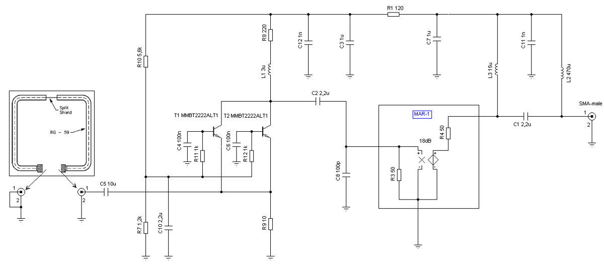 Illustrazione 1: Schematic circuit of the broad band antenna
The circuit is composed by thee main sections:
• low Zin front end
• amplifier stage
• power management
Lets see now, some deeper description.
In order to have a very low input impedance, the common base configuration is used. A quasi- parallel of two transistors permit to reduce furthermore the Zin. The idle working point of these devices is mostly set from the values of R7 and R10, while it’s stabilized by means of R9 which acts as a local negative feedback. R9 has also the task to damp the peak in response that the loop tends to have, while approaching its self resonating frequency (often placed around 30-40MHz). The two transistors have separate base biasing, in order to equalize their own intrinsic dispersion of static characteristic. This stage
has a little frequency compensation made by L1, with the goal to keep flat the response at higher frequencies. An alternative to the 2N2222A could be the BC849B or similar ones. The whole stage use about 20mw of power. The second stage has the task to amplify the signal and deliver it to the receiver (FCDpp) with constant output impedance. Nowadays, one of the most convenient solutions is the
use of a properly chosen MMIC. Luckily, many catalogs are plenty of “good offers”. The most common one is MAR-1 from MiniCircuits, well known for along time. The points of strength of this device
are: DC to 1GHz flat response, cheap, easy to find and low power. As a matter of fact, this old MMIC deliver almost 18dB of gain starting from DC (one of our key needs) drawing only 17mA from the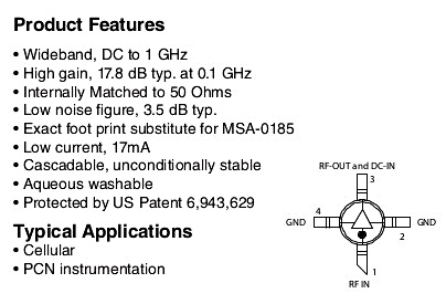
main. C8, act as a low pass filter to prevent overloading of the MAR-1 because of strong VHF signals. A choke of 15μH (not critical) on its output deliver lossless DC current to the device, while it represents an high impedance load ad radio frequencies. An interesting alternative to the MAR-1 that may be worth explore, is the much more modern SGA2386, which offers some better characteristics while having low need of power too.
Illustrazione 2: Summary of the MAR-1 specification and its pinout.Source: MiniCircuits site
The third part of the circuit is the power handling. In fact its duties are to separate the DC power from the signal line, bypassing to ground RF currents and distribute a proper and clean power to the active devices. L2 and a number of capacitors do those task easily and are in general not very critical.
All the circuit is boxed into a small plastic case of 60x37x20mm. On the bottom there is the SMA male
connector, intended to directly fit on the FCDpp input. On the sides of the box there are two connections for the loop. A suggested solution is the F (TV-sat) connector, because it’s cheap and easy to be found
with convenient installation.

Illustrazione 3: View of the front end while boxed
Building of the loop
The quickest way to make a loop is just as easy as to use a piece of properly shaped copper rod or wire. This solution will work well but. If you need to squeeze out the most in term of immunity from local noise sources, a shielded loop is what you need! One easy way to build it, is to use a piece of coax cable with
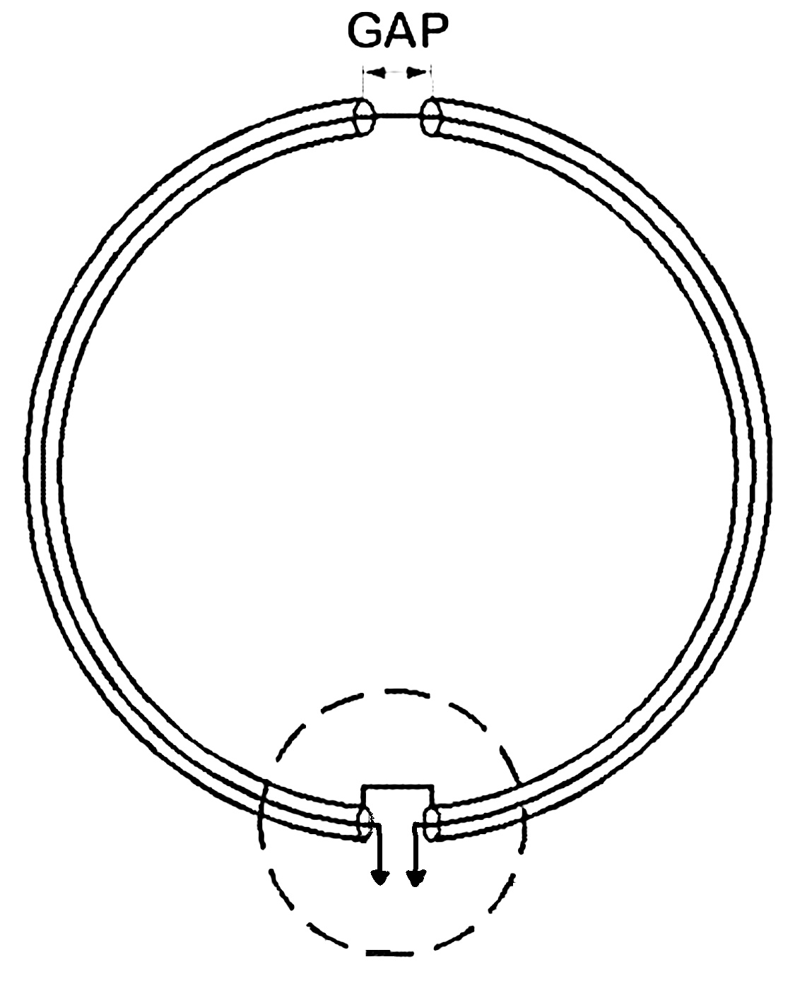
Illustrazione 4: Example of mechanical building of a shielded loop
“some strength”. The 7mm diameter TV-SAT cable is an idea, while semi rigid versions of coax could be even more convenient from a mechanical point of view. Somewhere, usually in the middle of the loop, the shield is cut away in order to open the magnetic circuit while the remaining part keeps working in order
to prevent strong E field from coupling with the receiving structure.
If you build the loop this way, its equivalent model for HF band (for 600mm diameter) is the following one:
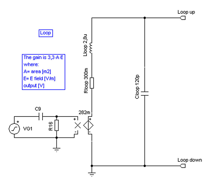 Illustrazione 5: Equivalent circuit of the shielded loop
The equivalent model is composed by the following lumped parameters:
• ideal current generator, proportional to the RF magnetic field and the capture area of the loop
• Rloop, which represents the losses, almost all, due to the resistance of the conductors
• Lloop, self inductance of the loop
• Cloop, which represent the parasitic capacitance of the structure
The loop used in this way has a nice, clean pattern with two broad main lobes and two nulls. Different from the Quad configuration (big loop!), this antenna has the nulls along the axes. A graphical representation could be seen below:

Pattern of a Quad antenna (big loop)
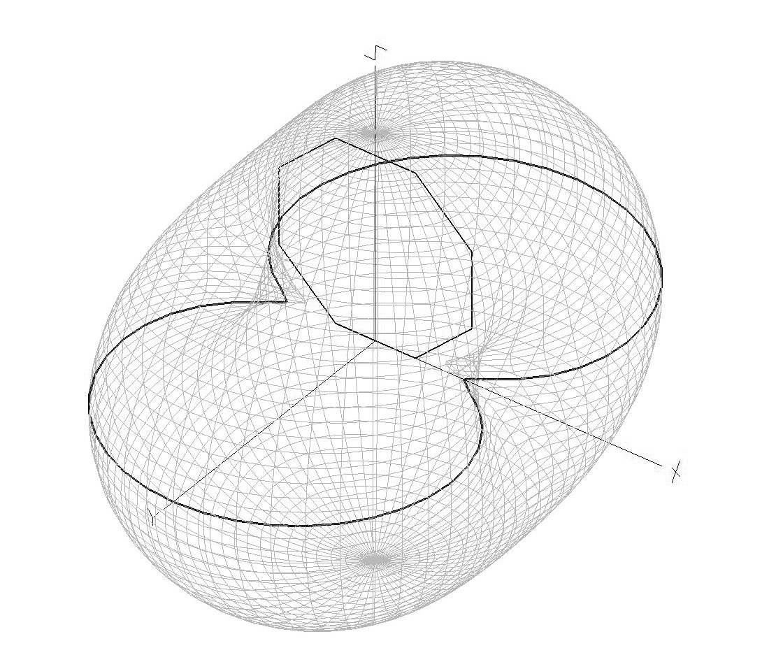

Pattern of a small loop
Simulation and measures
Once put all the gears together, it’s possible to simulate the global response of the system
as follow:
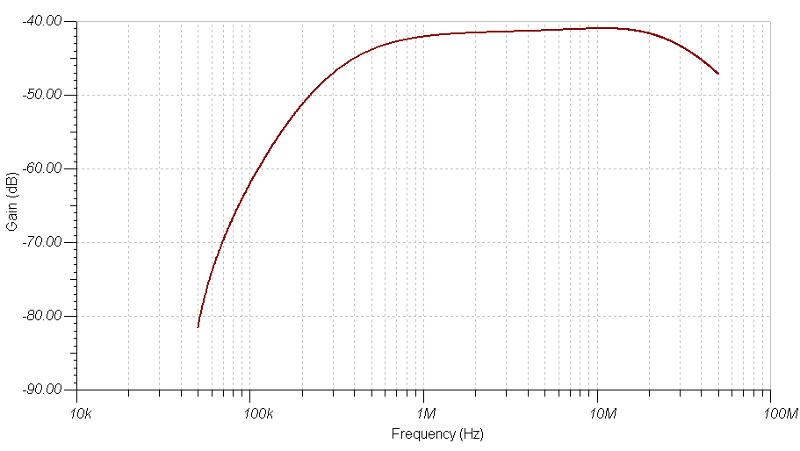 Illustrazione 6: Simulate response of the FunLoop
The curve clearly indicates a lower -3dB point at about 450kHz and an upper cut just above 30 MHz.
Okay, this is theory, but what about the real stuff? Let see now:

Illustrazione 7: Measured response of the FunLoop
The lower cut is about 480kHz, not far then from the simulation. The response at the higher frequencies does not decade as shown in the simulation because the loop at those frequencies isn’t “small” any longer and therefore the equivalent model used in the simulation do underestimate its sensitiveness. In fact, the FunLoop will be able to receive signals up to some hundreds MHz althogh with unforseenable response and pattern.
FM broadcasting and 144MHz ham band are in the capability of the system. Anyhow, it worths noting the very good flatness of the curve from LF up to the high end of HF.
A clue of what could be the result, could be seen in the following screenshot, taken with the FunLoop connected to my old netbook EeePC901 running HDSDR software and tuned on the 40m HAM band, while I was sit on my garden.

Illustrazione 8: Field test of the FunLoop: HDSDR and 40m tuning

Conclusions
This antenna will not do “miracles” but for sure will be an enjoyable friends of our field days with the Fun Cube dongle Pro Plus, allowing continues receiving capabilities from medium waves up to 2m band. The device is very convenient for holiday, on field demonstration, occasional use as well as back up solution when nothing better is available.
Credits
A big thanks goes to my Amsat-UK colleagues with a special mark for Howard G6LVB and to my friend Feng Xu, for helping me with the “British English”.
73, Pierluigi
Bibliography
Pierluigi Poggi: “Antenne Attive”, Sandit, Italy 2011
“The ARRL Antenna Book. Newington”, CT.: American Radio Relay League, 1998.
Carr, Joseph J.: “Small Loop Antennas for MW, AM BCB, LF and VLF Reception – Part 1.” Elektor
Electronics (UK), June 1994, pp. 58 – 63
Carr, Joseph J.: “Small Loop Antennas for MW, AM BCB, LF and VLF Reception – Part 2.” Elektor
Electronics (UK), July/August 1994, pp. 104 – 109.
Carr, Joseph J.: “Joe Carr’s Receiving Antenna Handbook”, 1994
Kraus, John D.: “Antennas”, New York: McGraw-Hill Book Co., 1950
Lankford, Dallas: “Loop Antennas Theory and Practice.” National Radio Club (USA). Reprint A-37,
1981.
Nelson, Gordon P. “High Precision Direction Finding of Medium Wave Skywave Signals.” National
Radio Club (USA), Reprint A-1 (repeat number, different paper), 1965.
KRAUS, J.D.: “Antennas” 2nd Ed. (McGraw-Hill Book Company) 0-07-100482-3, p. 251 (Section 6-
8)
John David Jackson: “Classical Electrodynamics” 3rd edition, Wiley: New York, 1998
C.-A. Balanis: “Antenna theory, analysis and design”, Wiley, 1997
www.minicircuits.com
amsat-uk.org
www.g6lvb.com
www.funcubedongle.com
ciao,
vorrei usare questo tuo progetto per un rx 470kHz WSPR (ora ho una PA0RDT che intermodula…)
https://iw4blg.info/2015/02/24/fun-loop-on204/
Visto che ho i 12V disponibili, ritieni che possa essere meglio dei 5V per quanto riguarda l’intemodulazione °??
Ho fatto alcune simulazioni con LTSPICE solo relative all’impedenza di ingresso/uscita a 470 kHz
12V:
impedenza ingresso: 1.24 OHM
impedenza uscita (tra C2 e C8): 145 OHM
corrente sulla R8 collettore: 33.5mA
5V:
impedenza ingresso: 3.5 OHM
impedenza uscita (tra C2 e C8): 220 OHM
corrente sulla R8 collettore: 4.9 mA
ti torna??
cosa ne pensi ??
grazie dell’attenzione e complimenti per i tuoi lavori.
73 de Mauro IK1WVQ
se mi rispondi mi avvisi per cortesia via Email ???
grazie 73
Mauro IK1WVQ
Ciao Mauro,
grazie dell’interesse. Quel progetto è ottimizzato al massimo per l’FCD, dove il principale vincolo è la pochissima potenza disponibile per alimentare l’antenna (max40ma @5V).
Se cade il vincolo dell’alimentazione, si aprono mille ottimi scenari.
Se sei curioso puoi provare sicuramente ad alimentarlo a 12V. Di certo andrà meglio e anche la risposta in basso migliorerà un poco. Verifica per scrupolo che le correnti non finiscano in zone pericolose per i dispositivi.Puoi anche aumentare il diametro della spira, come prima scelta per migliorare le cose.
Per andare oltre secondo me sarebbe poi da scegliere una configurazione un poco diversa che ho descritto nel mio libro http://goo.gl/AgI0XB che è quella che uso qui a casa con soddisfazione con la spira fatta con 1m di diametro di cellflex da 1/2″ e altri dispositivi. Tutto quanto detto è valido se parliamo di antenna a banda larga. Se nel tuo caso invece vuoi specializzarti nella ricezione a 470kHz, il consiglio è di farne una sempre a loop ma risuonante. Il vantaggio in sensibilità e reiezione dei segnali fuori banda è interessante. Ovviamente, paghi il prezzo che se cambi frequenza, devi risintonizzarla. Al momento non ho nulla di pubblicato (a parte un esempio didattico sempre nel libro, fatto con un tubo ed un Q multiplier), ma non credo sia difficile trovare qualche esempio “sano” in rete.
Per ogni cosa sono qua, nel limite del possibile.
Grazie e buona serata.
73, Pierluigi