
Yet another antenna for LEO satellites...
Purpose of this paper is to show how to modify and reuse an old antenna to make a convenient traffic with LEO amateur satellites using a stationary, omni directional aerial.
The starting point..
Discone antennas are pretty popular on the market as well as easily available for small prices, especially when second hand. Very often these antennas are discarded from the first owner because considered “deaf” and thus may offer a bargain opportunity.
This is a quite common misconception: often used with scanners having poor performances in term of sensibility and dynamic range, the final end could be rather disappointing, but.. do not blame (just) the antenna!
Discone aerials, are intended to be a compact, broad band antenna, derived from bi-conical version, very popular in the EMC/EMI labs.

The large band that it may cover, is a plus while paired with an instrumental or high grade receiver, while it may become a nightmare otherwise. The huge amount of out of band signals that this aerial can catch and bring to the input of the receiver is able to produce in the front end many intermodulation products, which in turn could be seen as “noise” or a desensing effect.
To talk with some figures on the hand, let see now how it behaves a generic discone. For this test I used a unknown brand antenna, bought for just few pounds on a flea market.
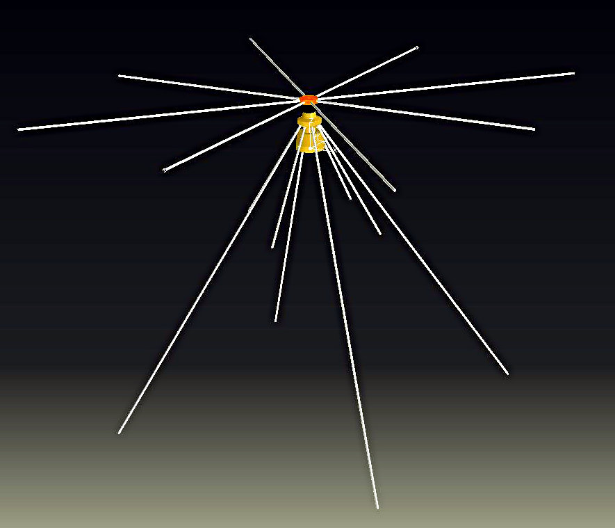
The central support of the antenna, is described on the drawing above.
The eight plus eight elements are respectively 273 and 820mm long, having 4mm diameter and the lower ring of radials has an inclination of about 60°.
To carry out some significant test, I installed it 3m high from ground on a 32mm diameter metallic pole with the all the setup placed on a quite meadow, in the countryside. To evaluate its return loss, I used my miniVNAtiny® that cover from a 1MHz up to 3GHz with reasonable accuracy once all the cables and joints are kept in consideration in the calibration.
Sweeping from 50MHz up di 1GHz I got the following curve of return loss:

As you could see, the antenna is “usable” (at least from a receiver point of view) from 100MHz up to several hundreds MHz, with many sub-bands of quite good impedance matching. So, signals from FM broadcasting, 3rd and 4th band TV, VHF DAB, and many point-to-point ground communication services are catch by the antenna and have a straight path down to the front end. However, if you wanna do two way communications, the return loss is often quite poor to fit a modern transmitter. So,this is the situation; quite nice if you have to do some radio monitoring for instance.. but if you wanna play in ham band with weak signals and cheap receiver, maybe also transmitting.. that's not the best way to go.
The idea
Luckily, with a very limited effort it's possible to modify this popular antenna with almost no cost and less than one hour of easy work antenna and get a nice one, trimmed on our purpose.
What we have to do, is just cut the elements as follow:
upper ring
4 pieces of: 154 mm
4 pieces of: 225 mm
lower ring
4 pieces of: 242 mm
4 pieces of 673 mm
Please note that also the rods diameter and the size of core of the antenna, plays a role in defining the right lengths of the elements, thus please take the above figures just as reference and foresee to dress off a bit. If you are unsure or whether you like to tune the antenna on another pair of bands, a convenient solution is to run the first tests using as radials some pieces of threaded bars. Very easy to get from any local hardware store, cut, join, cheap as well.
These sizes have been defined with the help of the software Mmana created by JE3HHT, DL1PBD, DL2KQ. For those who might be interested on, I'll be pleased to share the source file of my design: just drop me an email.


The simulated horizontal pattern is very good in both bands and we can really say: omnidirectional, which is very good. The vertical patterns are not as clean as we would like, but not be worried and consider the following facts:
I used some simplifications to define the antenna model
the antenna is simulated just 3m off the ground (consistent with practical use on field, not very good for pattern anyway)
the antenna is very simple and cheap
the loss of gain above 60-70° of elevation will not be a real issue with LEO satellites: if the bird is just over your head the signal will be very strong anyway..
the free Mmana version I've used is good, but it's not “perfect”
So, no panic and move on to cut the iron..
Please note to during installation of the new parts, the shorter four rods on the upper ring have to be paired with the shorter four ones of the lower set.
With this new set of rods installed in places of the original ones, let's see the new measurements:


Well.. the results are quite good! The Impedance matching is very good on both bands, while out of the ham frequencies the new antenna provides some degree of filtering protecting the front-end from overloading.

Illustrazione 8: Field test of the antenna next to my car
Field test
Illustrazione 8: Field test of the antenna next to my car
In order to complete the story, I practiced a bit with this antenna during my holiday, having it just next to my car. Results have been quite okay, not far from what I was expecting to get. Satellite communications have been smooth with minor QSB during the passes and always better that the one I could get with the dualband antenna on the roof of the car. Generally speaking, I’ve found this antenna rather convenient, once disassembled it’s very compact and easy to have with you, almost anywhere.
Conclusions
I hope this little work could be useful for testing, experimenting and practicing with amateur satellites. The cost is very little and the results pretty good. This antenna could be well considered for fixed installation and field-day operation as well. My best wishes of fun and I hope to catch you on the birds!
References
http://hamsoft.ca/pages/mmana-gal.php